Memory Management
last update: March 25, 2012
We are able to find everything in our memory, which is like a dispensary or chemical laboratory in which chance steers our hand sometimes to a soothing drug and sometimes to a dangerous poison.
— Marcel Proust, Remembrance of Things Past, vol. 10, "The Captive," pt. 2, ch. 3
Introduction
One of the most-demanded resources in computers (other than the CPU) is system memory. Every process needs it since a process’ code, stack, heap (dynamically-allocated structures), and data (variables) must all reside in memory. A processor reads instructions from memory and reads/writes data from/to memory. The functional interface of memory is:
- value = read(address): read the contents of memory location at address
- write(address, value): write value to the memory location at address
The memory manager is the part of the operating system that is responsible for allocating this resource to processes.
In a time sharing operating system, we we will need to allocate the system's memory among multiple processes. Moreover, we may need to deal with situations where we do not have enough physical memory and have to swap chunks of data between memory and secondary storage (disk). Systems in which we move (swap) entire processes between disk and main memory during execution are called swapping systems.
Linking: putting a program together
A program is a bunch of code and data (variables, which may be initialized or uninitialized). For a program to execute as a process, it has to be loaded into memory via a program loader. The executable file that contains the program consists of several sections that identify different regions of the program and where they should be loaded into memory. Common regions include executable code ("text"), initialized variables ("data"), and zero-filled variables ("bss"). Some executable files also contain sections for storing an application icon, language-specific strings, and digital signatures to validate that the file has not been modified. In addition to making room for these memory-resident sections, the program loader will have to allocate an area of memory for the program's stack, which stores return addresses of called functions, saved registers, and local variables and define an area for a heap, which stores dynamic requests for memory (e.g., malloc/free).
Complete programs are rarely compiled from a single file of code. In most cases, the program makes use of functions and variables that are external to the code in the file. For example, in C one is likely to use a printf function or system calls within a program. Neither of these are implemented by the user. Instead, they are located in libraries. If a program is compiled from several files, one file may refer to functions in another file and the other file may, for example, make references to global variables in the first file. The separately-compiled files are linked together to create the final executable file. Note that an executable program does not use symbol names; everything is be referred to by a memory address.
To handle the fact that an executable program will be assembled from several files, the compiler generates a a symbol table along with the compiled code for each file that it compiles. This symbol table contains textual names of functions and variables, their values (e.g., memory location or offset), if known, and a list of places in the code where the symbol is referenced. The job of a linker is to match up references to unknown symbols from compiled files (object file) with their known counterparts in another object file and generate a final executable file. The linker may also be provided with a library file, which is simply an archive (bundle, or collection) of object files that were generated from multiple source program files. The linker then searches through the archive to find the specific object modules that contain the symbols that need to be resolved (for example, the definition of printf). This entire process is called static linking. All symbols are resolved by the linker and any needed components from libraries are copied into the final executable file.
There are a few problems with static linking. One is that if a library changes (due to a bug, for example), then the version in the executable file is outdated. The second problem is that because many programs have a copy of common library elements (e.g., printf), the size of every program file is that much bigger. This is also reflected in the executable process: even if multiple processes use the same code, each must have its own copy. The desire to remedy this led to dynamic linking and shared libraries.
Dynamic linking is just-in-time linking. Instead of relying on a linker to put everything together into one executable program, the linking (cross-referencing of known and unknown symbols and placement in memory) is deferred to program load time. The static linking phase resolves symbols against a stub library instead of one that contains the actual library code. On first reference, the stub function in the linked library calls the operating system loader to load the actual function from the dynamic library file into memory, relacing the stub reference with the actual function.
Dynamic linking does not solve the issue of every process' use of a library consuming system memory. If twenty processes each use the printf function, each one will have its own copy of the code that implements it. Shared libraries add text (code) sharing onto dynamic linking. If a program needs to use code from a dynamic library, the stub function checks whether the needed library component is in memory. If not, the stub requests that the operating system loader load it. As with dynamic libraries, the stub is then replaced with the address of the library. If the shared library is already in another process' memory, the operating system creates a read-only shared memory region among the processes so that each process will have that code in its address space. To share this memory among multiple processes means that we will need to reserve a region of memory for shared libraries. Because different libraries may be loaded in a different order, we cannot predict what specific location a library will be loaded into. For this reason, it is important that shared libraries are compiled with position-independent code, containing only relative memory references instead of absolute addresses.
Single partition monoprogramming
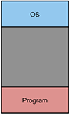
Figure 1. Single partition monoprogramming
The easiest system to design is one in which we allow only a single program to be run at a time and keep only that process in memory. The process effectively takes over the memory space of the machine, with only a portion of memory devoted to the operating system. Early computer systems and early microcomputer operating systems adopted this solution. For example, MS-DOS kept the operating system in lower memory and the operating system and device drivers (the Basic I/O System, or BIOS) in the upper 8K bytes of the 8086 processor's one megabyte address space. The rest of the memory was available to the executing process.
Multiprogramming
Giving the machine to one process and keeping just that one process in memory does not work if we want to run multiple programs concurrently. We really wanted to have the illusion of running multiple processes at once and provide users with interactive response to processes. Swapping an entire process between memory and disk each time we context switch would be prohibitively expensive (disks are insanely slow compared to memory).
CPU Utilization
The other incentive for keeping more than one process in memory is that of trying to keep the CPU busy as possible. Many processes spend a lot of their time — often most of their time — waiting on I/O. It would be great for the CPU to be able to switch to another process that is already in memory and in a ready state when the currently executing process has to block.
If we assume that the average process spends 20% of its time computing (and 80% blocked, waiting on I/O) then the processor is unused 80% of the time. One could then speculate that if we kept five processes in memory we could achieve 100% CPU utilization. However, that means assuming that no two processes wait on I/O at the same time. More realistically, we can assume that if a process spends some fraction of time, p, blocked on I/O and there are n processes in memory at one time then the probability that all n of them are waiting for I/O (hence making the CPU idle) is pn . This means that the percent of time the CPU is not idle is 1–pn. This is known as CPU utilization and n, the number of processes in memory at one time, is known as the degree of multiprogramming.
For example, if we have one process in memory and it is waiting on I/O 80% of the time (p=0.8, n=1), then the CPU utilization is 1-0.81, or 20%. If we have three such processes in memory at once, the CPU utilization increases to 1-0.83, or 49%. With ten processes in memory, the CPU utilization soars to 1-0.810, or 89%. This analysis is, of course, only an approximation to help us understand the value of multiprogramming. In reality, all processes do not spend the same amount of time waiting on I/O but we can see that, in most cases, if we can have more more processes sit in memory at once, we increase CPU utilization.
Positioning code and addressing memory
We want to have multiple programs loaded in memory at the same time and have the operating system periodically switch the processor's execution state from one process to another. This means that each program will be loaded into different areas of system memory. Since programs use memory addresses for jump instructions and memory references, they need to make sure that the proper address is used no matter where the program is positioned in memory.
The most basic approach is that of absolute code, where all addresses are hard-coded into the program and the program knows its starting memory location. For example, the CP/M operating system loaded all programs at the starting address of 0x0100. If we want to place multiple programs in memory at the same time, this becomes problematic since we are not likely to know a priori where the program will be loaded into memory.
Another approach is to have the compiler generate position
independent code. In this model, all references to memory
that the program uses are relative to either the current location
or to the stack pointer. Any attempt to use absolute addresses to
reference the program's data or instructions must be avoided since
it will yield unpredictable results because, as with absolute code,
the program does not know where it will be loaded into memory.
With the gcc compiler, the -fPIC option
will generate position independent code.
A compiler can generate code that does not fill in memory references. Instead, it generates a relocation table. In the simplest case, this is a table of byte offsets into the program that represent locations where absolute memory references exist. The program is compiled (or assembled) to assume a base address of 0. When the operating system loads the program, the table is traversed and each memory reference within the program gets the base address of the program added to it. This is known as dynamically relocatable code.
Logical Addressing
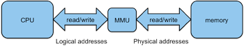
Figure 2. Address translation
A radically different approach to positioning code in memory is to introduce support into the computer's hardware that will translate any address reference made by the process (the logical address) into its actual location in physical memory (the physical address, or real address). This translation is done as the program executes. A memory management unit, or MMU, is responsible for performing this real-time, on-demand translation between logical and physical addresses.
Relocatable addressing
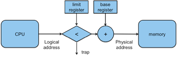
Figure 3. Base & limit addressing
A direct approach to a hardware solution is to offset each memory reference by a base address — a constant value that represents the starting memory location into which the program was loaded. Now a program can assume that it starts at location 0 (or some other known location). When the operating system loads it into some other region of memory, say location 20000, the operating system would load the base register of the memory management unit with the value 0f 20000. When the program references location 1533, the memory management unit will add the base register to the reference, resulting in a reference to a real memory address of 21533 (20000+1533). To ensure that the program does not access memory outside its range, a test for a limit can be added. This is the total amount of memory that is allocated to the process. If the logical address exceeds this limit, then the memory management unit will generate a trap.
Multiple fixed partitions
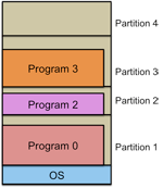
Figure 4. Multiple Fixed Partitions
Getting back to the issue of loading multiple processes into memory at the same time, we can divide memory into multiple fixed partitions (segments). The partitions could be of varying sizes and they would be defined by the system administrator when the system starts up. This was the approach used in IBM System/360's OS/MFT. A new program gets placed on a queue for the smallest partition that can hold it. Any unused space within a partition remains unused. This is internal fragmentation.
If any partitions have no programs to run then the memory in that partition is always wasted. This is called external fragmentation. External fragmentation refers to areas of storage that are not allocated and are therefore unused. A modification of the multiple queue approach is to use a single queue. All incoming jobs go on this queue. When a partition is free, the memory manager searches the entire queue for the biggest job for that available partition. This gives small jobs poor service, a problem that can be partially remedied by defining more small partitions when the partitions are configured. Overall, a system using multiple fixed partitions is simple to implement but does not make good use of memory. It also messes up the scheduler's decision of what processes should run since partitions dictate which processes could be loaded into the system in the first place. Finally, this method of allocation requires knowing just how big the process will get. If there isn't enough room in the partition, then the operating system will have to move the memory contents into a larger partition (if available) or, if no partition is available, then save the partition contents and processor register state onto some temporary storage on the disk and queue the process until a larger partition becomes available.
Variable Partition Multiprogramming
Given that memory is a highly desirable resource, multiple fixed partitions isn't a desirable approach due to internal fragmentation (programs are rarely a perfect match for the partitions they go into, leading to wasted memory) and due to the problem of deciding what partition sizes to create (lots of small partitions? A few small and a few medium sized ones? A couple of big partitions?). An improvement over multiple fixed partitions is variable partition multiprogramming, where partitions are created dynamically as they are needed and to the size needed.
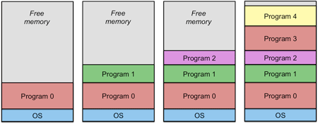
Figure 5. Variable partition multiprogramming
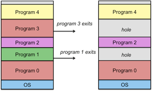
Figure 6. Holes in variable partition multiprogramming
Consider the example in figure 5. As new processes get created, the operating system allocates each process into available memory and is given the exact amount of memory required by the process. As processes exit (figure 6), they create holes: regions of free memory. When new processes get created, the operating system tries to fit a process into an available hole. If a fit is found, it is unlikely that the new process will be the exact same size as the previous one (and it cannot be bigger), so a smaller hole will be left. We can combine the holes (unused memory) by relocating processes down (move process 2 to the top of process 0 and then move process 4 to the top of the relocated process 2). This is known as memory compaction and is usually not done because it takes up too much CPU time.
Growing processes
Many processes typically start off small and grow through their lifetime. The size of the stack may increase as a process allocates more local storage and executes multiple levels of functions. The heap starts off empty and grows as a process requests more memory. If a process is located next to a hole (unused memory), there’s no problem. All the memory manager has to do is adjust the top of that process’ partition (the limit register). If not, we have a problem. The process wants to grow but there is no room. We can only do two things: if there is a big enough hole in memory, then we can relocate the process into that larger hole. If there isn't then processes would have to be swapped out onto the disk to create a hole. If there is no swap space left on the disk and there is no large enough hole, the process will have to be killed.
Since the operating system can reasonably expect processes to grow, it's good practice to allocate extra space in memory. When we swap the process out to disk, we swap out the space that the process is using. When we swap the process back in, we add on the same extra space. For example, suppose we allow for a 20% growth and have a process whose size is 100 KB. We allocate 120 KB for this process. If the process needs to grow to 140 KB and there's no free memory block, then the 120 KB process is swapped out. When it's swapped in, we try to find a hole for 140 KB + 20%, or 168 KB.
Segmentation
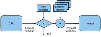
Figure 7. Segmentation hardware
A variation on variable partition multiprogramming is to allocate each of the components of a process separately (e.g., code, data, heap, stack). This is known as segmentation. By taking this approach, we break up a process into smaller chunks and increase our chances of finding free memory. Certain regions, such as code and static data, will not grow in size and will never have to be reallocated. It's unlikely that the entire process will have to be moved to a larger whole but rather just the heap or stack segments. To get this to work, however, means that we cannot use a single base register to offset all memory operations. The offsets are different depending on which segment of the process is being addressed. The memory management unit that handles segmentation has to take this into account. Each process will have a number of segment registers associated with it, one for each region of the process (e.g., code, data, stack). The processor's hardware will need to be designed to select the appropriate register for each type of memory reference. An example of processors that support a segmentation model is the family of Intel processors starting from the 8086 and 8088 and continuing through today's 64-bit systems.
Allocation algorithms
If more than one region of memory is able to accommodate a segment (or process), the operating system needs to make a decision on how to pick the best segment. Several approaches are possible.
- First fit
- Scan segments of memory until you find a hole that fits. Break the hole into one segment for the process and another segment that will be a hole containing the leftover memory. This algorithm has the advantage of a small search.
- Next fit
- This algorithm is just like First Fit except that it searches from where it left off the previous time (and then wraps around). In practice it exhibits worse performance than First Fit.
- Best fit
- The Best Fit technique searches the list for the hole that best fits the process. It’s slower than First Fit since the entire list must be searched. It also produces tiny holes that are often useless.
- Worst fit
- Since best fit doesn’t perform well, you would think its inverse would. The Worst Fit algorithm searches for the largest hole on the assumption that the hole remaining after allocation will be big enough to be useful. It also doesn’t yield good performance.
- Quick fit
- The Quick Fit algorithm maintains separate lists for common sizes (e.g. 4K holes, 12K holes, ...). It's fast but has the drawback that finding neighbors for merging is difficult.
Page-based virtual memory
All of the techniques we discussed were used in early operating systems. With a partition-based approach, handling fragmentation was always problematic. Moreover, processes were limited to the amount of physical memory available and the number of processes in memory could never exceed the size of available memory. If you needed to run more processes, you had to swap the contents of an in-memory process out to disk and swap in another process — and deal with memory allocation issues in doing so.
Paging is a memory management technique that:
- does not let the amount of physical memory limit the size of our process.
- allows the process feels like it owns the entire address space of the processor.
- allows memory allocation to be non-contiguous and has no external fragmentation problems, simplifying memory management and obviating any need for compaction.
- lets us keep more processes in memory than the sum of their memory needs so that we can keep the CPU utilization as high as possible.
- lets us us keep just the parts of a process that we're using in memory and the rest on the disk.
If the blocks that we divide memory into are all of equal size, then we have a paging system. If the blocks are of different sizes, then we have a segmentation system. In this section, we will examine how paging works. Implementing this requires a more sophisticated memory management unit architecture in the processor.
With paging, we divide physical memory into equal-sized blocks. These are called page frames. A logical address space is also divided into blocks of the same size, called pages. Every memory access is translated from a page to a page frame by the memory management unit. A page may be placed in any available page frame. The memory management unit maps a page to the page frame in which that page resides. The size of each page is constant and is a power of two. Therefore, a fixed number of high bits in the memory reference (virtual address) identifies the page number and a fixed number of lower bits in the address identifies the displacement, or offset.
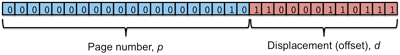
Figure 8. Virtual address decomposition
For instance, if the page size is 4K bytes, the offset in the page will be 12 bits (log24096 = 12). This means that if we have a 32-bit virtual address, the page field will be 20 bits (32-12), corresponding to 1M pages. An address of 0x00002c37 will correspond to page 2, offset 0xc37. If this isn’t obvious, convert the address to binary. Grab the top 20 bits as the the page number and the bottom 10 as the offset (figure 8).
When a process references a virtual address (v=(p,d)), the paging system (the MMU) looks up p in a page table using the page number as the index into this table. The page table is an array of page table entries (PTEs). A page table entry (PTE) for page p in the table contains a page residence bit that indicates whether the page is currently mapped onto a page frame. If it is, a field in the PTE provides the page frame f. The pseudocode for this operation is:
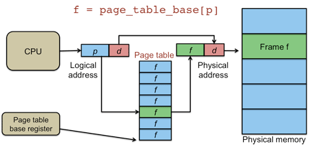
Figure 9. Page table lookup
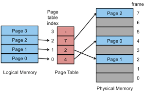
Figure 10. Page mapping
The physical location of the data in memory is therefore at offset d in page frame f: the address that is the concatenation of f and d (figure 9). If the page is not mapped to a page frame in memory, a page fault occurs (this is a trap to the operating system) and the OS is responsible for either killing the process (in the case of an invalid memory reference), allocating the page or loading the needed page into an empty page frame and then restarting the faulting instruction.
Because any page can be mapped into any page frame, there is no need to allocate memory contiguously. Any available page frame can be used for any page and the page table keeps the mapping, providing the illusion of one contiguous block of memory (figure 10).
Direct mapping
The page-table based system just described is a direct mapped paging system. With a paging system that uses direct mapping, the page table contains an entry for every page (page table entry, or PTE) in the process' virtual address space. The most significant bits of the virtual address are used as an index into the page table. Before starting a process, the operating system loads the starting address for the page table for that process into a page table base register. Ideally, the page table should be in high speed memory so that the page translation can be done within an instruction cycle. Unfortunately, the page table can be somewhat large (e.g., a 4 GB address space and 4 KB pages yields a page table of 1M entries) — and you need a page table per process. Hence, it is not feasible to use memory that's on the MMU (integrated into the CPU chip). If we use main memory, however, we end up spending an extra memory access cycle accessing the page table. The effective speed of every machine instruction that makes a single memory reference is now twice as slow!. An instruction that makes two memory references now has to make four. We need something better.
Associative mapping
Associative memory, also known as content addressable memory, is very high speed, expensive memory that, unlike regular memory, is queried by the contents of a key field versus an address-based lookup.
Within the memory management hardware, associative memory is used to construct the translation lookaside buffer, or TLB. Each entry in the TLB contains the information that would be found in a page table as well as the page number (which is used as the query key). Every entry in the TLB is compared with the key (the page number that we are looking up) simultaneously. This approach is known as associative mapping.
Associative memory is fast but also expensive (more transistors and more chip real estate). For it to work well, it has to be co-located in the processor's memory management unit. Given how big page tables can get and that we need a page table per process, the the TLB will not be used to store entire page tables but rather act as a cache for frequently-accessed page table entries instead. This is a combined associative and direct mapped approach to page translation and is used by practically every processor being made today.
The hope with the TLB is that a large percentage of the pages we seek will be found in the TLB. The percent of references that can be satisfied with a TLB lookup is called the hit ratio. A hit ratio close to 100% means that almost every memory reference is translated by associative memory. Ideally, the TLB will be designed to be fast enough to allow the CPU to do the logical-to-physical memory translation as well as the corresponding real memory read/write operation in one memory access so that the MMU does not create a performance penalty. Unlike normal cache memory, the TLB is built into the MMU and caches individual table entries rather than a set of arbitrary memory locations.
If a page is not in the TLB, then the MMU detects a cache miss and performs an ordinary page lookup (referencing the memory-resident page table). In doing so, one entry is removed from the TLB and replaced by the entry that was just looked up so that the next reference to that same page will result in a TLB hit.
Address space identifier
Every process has its own page table (since every process has its own address space). However, there isn't a TLB per process. When a process runs, it should not be allowed to access other process' memory through the TLB. We can do two things. The easy solution is to clear all valid bits in the associative memory, thereby invalidating the entire TLB whenever a new process starts running. This makes context switches costly since a the first several memory references of a process will be forced to access the in-memory page table.
A cleaner solution requires modifying the TLB hardware by adding another field in it to identify the process for which the memory mapping is valid. This field is called the address space identifier, or ASID. A hardware register also has to be added to the processor that will allow the operating system to set the ASID during a context switch. When doing a TLB lookup, the MMU hardware compares the process ID register with the TLB field to only accept matches from the proper process. This solution allows us to save time on context switches since there's a chance that the TLB already contains mappings of frequently used pages for the switched-in process.
Memory protection and statistics
In addition to managing logical-to-physical memory page translations, each page table entry can contain fields for additional information, allowing the management unit to enforce memory access permissions and track memory access. Some common elements in a page table include:
- valid/invalid: (residence bit) is there a page frame mapped to this region of memory?
- read-only: is the process allowed to write to this page?
- execute: is the process allowed to execute code from this page?
- dirty: has the page been modified since the bit was cleared?
- accessed: has the page been accessed since the bit was cleared? This can help us decide if a page is still being actively referenced.
Sharing memory
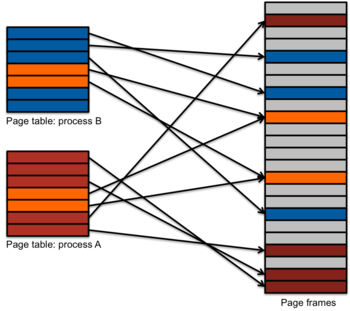
Figure 11. Memory sharing
While a virtual memory system allows each process to have its own private address space and ensures that a process cannot stray into any regions that have not been explicitly mapped in the page table, it also makes it easy to share regions of memory. By simply having page table entries for different processes point to the page frame, the operating system can create regions of memory that are shared by two or more processes (figure 11). The only caveat is that the shared regions have to be multiples of a page; fractional pages cannot be shared. In doing this, the operating system is responsible for keeping track that certain page frames belong to multiple processes. Shared page frames should only be considered unused when the last process that has them mapped exits.
Multilevel page tables
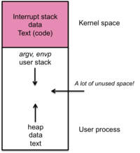
Figure 12. Per-process memory map
Virtual memory allows each process to have its own private address space. The page table for the process maps memory references from this virtual private address space onto page frames in real memory. Because a process can conceivably access any memory location in its address space, the page table has to be big enough to cover every page within that space, whether that page is actually mapped to real memory or not. As we saw earlier, a 32-but system with 4 KB pages means that we have 20-bit pages and, therefore, a 20-bit index into the page table. This means that the page table needs to have 1,048,576 (220) entries. Even if we skimp on extra flags and assume that each entry is only 24 bits, the page table now consumes 3 MB per process (with a 64-bit address space, each page table will consume approximately 28,672 TB!).
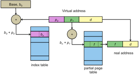
Figure 13. Multilevel page table
The vast bulk of processes use only a very small part of their address space, although the regions that are used may be scattered. For example, the stack may be at a different end of memory than the text and heap (see figure 12). It's a waste to maintain an entire page table since large regions of it will be unused and empty.
To optimize memory use for a sparse page table, we can arrange the page table in a hierarchy (figure 13). The virtual address is divided into three parts (figure 13). The high-order bits index into a top-level page table (index table). This table contains the base address of a partial page table: the pages that contain those high-order bits. The middle-bits are an offset into this partial page table. This partial page table contains page table entries. If a large-enough region of memory is not used, then the partial page tables for those regions don't need to be created and the corresponding entries in the index table can indicate that there is no valid mapping.
Inverted page tables
The hierarchical approach helps to deal with large address spaces. The hierarchy can be extended to additional layers (e.g., a three-level or even a four-level page table) at the cost of an extra memory read per table lookup. A four-level page table will require four memory reads just to find the page translation and then one more memory access for the actual read/write operation. This effectively makes memory access five times slower whenever there's a cache miss.
With a large address space, the potential number of pages is huge with a larger address space (e.g., 64 bit). The number of page frames, however, is more manageable since it is limited by the physical memory on a system. We can design a paging system that is indexed by page frames such that the ith entry into an inverted page table contains information on the contents of page frame i. The number of entries in such a table will always be equal to the number of page frames on the system and will be independent of the virtual address space or the number of processes. The problem is that it is expensive to search through such a table since there is no direct index onto the desired entry; we only know the page number but the table is indexed by page frames. By using a hash table, we can achieve an access time that is much better than linear search through the table. Moreover, we can couple this inverted page table with a TLB as we did with with page tables to gain the benefits of cached entries for frequently accessed pages. Inverted page tables are not used on today's x86-64, Intel 32-bit, or ARM architectures but have been used on systems such as the IBM System/38, PowerPC, Intel Itanium, and UltraSPARC.
Logical and physical addressing modes
Most processors support operation in two modes: virtual addressing mode, which uses address translation through the memory management unit, and physical addressing mode, which bypasses the MMU. In this latter mode, every memory reference is a reference to the actual physical memory location in the memory system. Upon power-on, a CPU will start up in physical addressing mode since page tables have not been set up yet. The system will usually remain in physical addressing mode while the operating system is loaded and run to initialize the page table. The operating system will then switch the processor to virtual addressing mode.
System memory map
In today's operating system, the view of memory is split into two logical regions: kernel memory and process memory. Kernel memory is the memory that is reserved for the operating system kernel's code, data, and stack. Its location in the virtual address space remains constant, typically in the top part of the address space. On 32-bit Linux systems, kernel memory is configurable (PAGE_OFFSET) and is generally set to the top 1 GB of the address space. On Microsoft Windows 7 systems, the top 2 GB of the address space is dedicated to kernel memory on 32-bit systems (8 TB on 64-bit systems).
Process memory represents the remainder of the address space and is available to user processes. In physical memory, page frames will be allocated to various processes. In virtual memory, however, we are looking at memory from the viewpoint of the context of the process. The view of memory is defined by the page table for the process and contains mappings to the pages relevant to that specific process as well as mappings to the kernel.
When a mode switch occurs, either because of an interrupt or system call, the current page table does not change: we experience a mode switch and not a context switch. Execution is transferred to the kernel, which can, if it needs to, access memory in the context of the process that generated the mode switch. A page table will generally be set up to disallow user-mode execution access to regions of the address space that are mapped to kernel memory. Most memory management units allow one to set kernel-only access permissions to a page.
Page allocator and kernel memory management
With page-based virtual memory, processes can freely get available discontiguous pages as they need more and more memory. The page table for a process can provide the illusion of contiguity by making the virtual address space contiguous. There are special cases, however, where physically contiguous pages are needed. For example, devices that use DMA (direct memory access) interact with memory over the system bus and hence bypass the processor and its memory management unit. If devices on the system rely on DMA, it is crucial that all DMA operations take place either within a page or across contiguous pages. For this reason, it is useful for an operating system to be able to handle requests for contiguous pages for those special cases when such pages are needed. For the most part, these allocations are requested for kernel memory space.
To add to the complexity, some computer architectures (e.g., older Intel) allow peripherals to perform DMA only for addresses below 16 MB. Linux deals with different memory requests via a zone allocator, where a request for memory is accompanied by an prioritized list of acceptable "zones", or types, of memory. The three currently supported zones are:
- DMA: memory that is accessible for DMA.
- NORMAL: general purpose memory
- HIGHMEM: memory regions strictly for system use (e.g., file system buffers, user space, etc.)
For most of today's computer architectures, there is no distinction between the regions.
To keep track of pages, the Linux operating system uses a technique called the Buddy System within each zone and maintains an array called free_area of lists of free pages. The first element of the array is a list of free single-page regions; the second element is a list of free two-page regions (free adjacent pages); the third element is a list of free four-page regions; etc., up through the tenth element, which contains a list of free regions of 512 contiguous pages.
The Buddy System
The buddy system is a memory allocation and management algorithm that manages memory in power of two increments. This brief discussion presents only the basic buddy algorithm; there are a number of variations on it. lists of blocks of free chunks of memory.
A memory manager (e.g., the Linux page allocator) using the Buddy System keeps lists of free blocks that are sizes of powers of two (2, 4, 8, 16, 32, …). Initially, when all of memory is free, all lists are empty except for the largest power of two that is less than or equal to the size of allocatable memory. When a block of size n is needed, the algorithm checks the list for the nearest power of two that is greater than or equal to n. If there is one, all is well and the block can be marked as used. If there is no free block, the algorithm gets a block from the next level, splits it into two buddies (which get recorded in the previous level of the list), and uses one of those for allocation. When that block is freed again, the buddies can be combined and brought back up to the next level in the list. If the next level in the list does not have an available block, the process is repeated with successively bigger-sized blocks in the list.
For example, suppose we're using a buddy-based page allocator and need a block of 53 contiguous pages. The closest bigger power of two is 64, so we request a 64-page chuck. Suppose that all we have is one free 512-page segment. We have an array of pointers to lists: a 512-page list, a 256-page list, etc., down to a 1-page list.
The algorithm starts off by looking looks for a 64-page segment. That list is empty, so it then attempts to get a 128-page segment that it can split into two 64-page buddies. That doesn't exist either, so we then look for a 256-page segment. We don't have it, so we then look for a 512-page segment. We have one of those and split it into two 256-page buddies. Now we back up and look for the 256-page segment that we couldn't find earlier. Now we have two of those. We grab one and split it into two 128-page buddies. We back up further and look for that 128-page segment. We have two of those now and split one into two 64-page segments. We back up further to our initial search for a 64-page segment and, lo and behold, we have one we can allocate.
When a segment is freed, the algorithm checks to see whether the segment's buddy is free as well. If it is, then the two buddies are combined into a single free segment. The process is repeated for progressively bigger segments until there are no more buddies to consolidate.
This algorithm is fast and makes merging very easy. Unfortunately, because it requires all allocation units to be powers of two, it is wasteful of memory since it can lead to internal fragmentation. Recall that unused memory within an allocation unit is known as internal fragmentation and unused memory between allocation units is known as external fragmentation.
Slab allocator: memory allocation for objects
A lot of memory allocation needs are not for entire pages or groups of pages but for the dynamic allocation of specific objects. The Linux slab allocation is an example of a memory allocator designed for managing dynamic kernel objects (e.g., semaphores, network socket buffers). The design goal of the slab allocator is to preallocate regions of contiguous memory to make it efficient to service allocation requests for specific objects.
A slab is one block of contiguous memory, often several pages in size. Each slab is responsible for handling allocation requests for objects of the same size. Because a slab handles equal-size objects, there are no fragmentation problems. In the language of the slab allocator, a cache is the term for a collection of slabs responsible for a specific object. Each slab may be in one of three states:
- Empty: all objects in the slab are free. This means that the collection of pages that make up this slab can, if needed, be reclaimed by the operating system for other purposes.
- Full: all objects in the slab are in use.
- Partial: the slab contains both free and in-use objects.
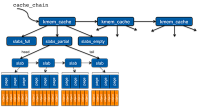
Figure 10. Linux slab allocator
The slab allocator is a linked list of caches (kmem_cache).
A variable, cache_chain points to the start of this list.
Each cache within the list is identified by the type of
object for which it is responsible.
Within each kmem_cache structure are three pointers:
one to a list of full slabs, another to a list of partial slabs,
and one to a list of empty slab. Each of these represents a linked
list of slab objects.
Some of the basic operations on a slab are:
- kmem_cache_create
-
Creates a new cache. This operation is typically used when the
kernel initializes or when a kernel module is loaded.
It identifies the name of the cache and size of its objects.
Separate caches for inodes, directory entries, TCP sockets, etc.
On a Linux system, you can see
all the configured slab types and their allocation status in
the file
/proc/slabinfo. - kmem_cache_destroy
- Destroy a cache. The pages used by the cache are reclaimed by the page allocator. This is typically called by a module when it is unloaded and the specific objects created by that module will no longer be needed.
- kmem_cache_alloc / kmem_cache_free
-
Allocate an object from a named cache. If there are no free
or partial slabs available, the allocator will call
cache_alloc_refillto add additional pages to the slab. The functionkmem_cache_freemarks the object as free. - kmalloc / kfree
-
This is similar to
kmem_cache_allocexcept that no cache is specified. The function iterates through the list of caches until it finds one that can satisfy the requested size. Linux configures the slab allocator with generic caches of a variety of common sizes (e.g., kmalloc-8, kmalloc-16, kmalloc-96, kmalloc-256). Thekfreefunction marks the allocated object as free.
MMU Summary
A memory management unit that supports paging causes every logical address (virtual address) to be translated to a physical address (real address) by translating the logical page number of the address to a physical page frame number. The page number comprises the high bits of the address address. The low bits of the address form the offset within the page (or page frame). For example, with a 64-bit address, if a page size is 1 MB, then the lowest 20 bits (which address 1 MB) form the offset and the top 44 bits form the page number.
Page-based virtual memory is cool. It alleviates the operating system from having to find contiguous regions of memory to house a process; any available memory pages could be used. The page table keeps track of the mapping between the virtual and physical address spaces. Every process can feel like it owns the full address space of the processor.
The problem of external fragmentation is completely eliminated. Internal fragmentation exists where there is unused memory within a page. Larger pages make for smaller page tables and use the TLB more efficiently but create more internal fragmentation.
The page table also allows the operating system to manage memory protection and define specific pages as writable or as containing executable code. Because each process needs a page table, the operating system needs to set one up when it first creates a process. After that, it can switch address spaces during a context switch simply by changing the page table base register and, if the MMU supports it, the address space ID register.
Thanks to a memory management unit, every process can have its own address space. The same virtual address may refer two different page frames (physical memory locations) for two different processes because each process has its own page table. The operating system is responsible for managing the page table for each process. During a context switch, the operating system has to inform the processor's memory management unit that it has to use a different page table. It does this by changing the page table base register, a register that contains the starting address of the page table.
Two optimizations are typically present in memory management units: one optimizes lookup time and the other optimizes the space used by the page table.
-
If every address translation required a lookup in a page table then our memory access performance would be twice as slow since we'd need to read the page table in addition to accessing the memory location that we want. This overhead is reduced by a translation lookaside buffer, or TLB, which caches frequently-used page table entries in its associative memory.
-
Because most processes use only a small fraction of the available virtual address space, there will be large regions of a page table that will contain no entries. To keep the size of a page table more manageable, a multi-level structure is often used. The page bits of a virtual address are split into two parts: the high bits define the offset into a top-level index table. This index table contains base registers for partial page tables. The low bits of the page bits define the offset within that partial page table.
References
- John R. Levine, Linkers and Loaders, Morgan-Kauffman, October 1999, ISBN 1-55860-496-0. Linkers and Loaders, John R. Levine
- Intel Software Developer's Manual (Download site)
- Inside Intel® Core® Microarchitecture and Smart Memory Access, Jack Doweck, Intel Corporation, 2006. Product Brief: Intel® CoreTM2 Duo Desktop Processor, Intel Corporation, 2008.
-
ARM1176JZ-S Technical Reference Manual, Revision r0p7,
Chapter 6: Memory Management Unit.
(pdf version) - Physical Address Extension, Wikipedia article
- x86-64, Wikipedia article
-
Four-level page tables merged, LWN.net article
Also, see: 4level page tables merged into mainline, LWN discussion - Anatomy of the Linux slab allocator, M. Tim Jones; IBM developerWorks, May 2007.